| Critical Point Drying | ||||||||||||||||
| Introduction
Critical Point Drying is an established method of dehydrating biological
tissue prior to examination in the Scanning Electron Microscope. The technique
was first introduced commercially for SEM specimen preparation by Polaron
in l970. The original design concepts which included a horizontal chamber,
are still embodied in the design of the E3000 and E3100 CPD systems. These
two units have found general acceptance in many laboratories throughout
the world. Together these Critical Point Dryers offer the user a choice
most suited to the particular specimen preparation requirements.
|
 |
|||||||||||||||
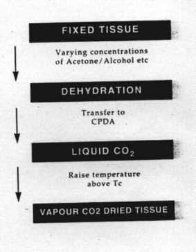
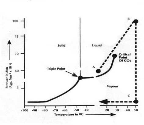
| The Critical Point Drying
Method
The phase diagram shows the pressure to temperature ranges where solid, liquid and vapour exist. The boundaries between the phases meet at a point on the phase diagram called the triple point. Along the boundary between the liquid and vapour phases it is possible to choose a particular temperature, and corresponding pressure, where liquid and vapour can co-exist and hence have the same density. This is the critical temperature and pressure. Critical Point Drying relies on this physical principle. The water in biological tissue is replaced with a suitable inert fluid whose critical temperature for a realisable pressure is just above ambient. |
 |
|||||||||||||||
| The choice of fluids is severely limited and Carbon Dioxide is universally used today despite early work with Freon 13 and Nitrous Oxide.With CO2 a critical point of approximately 35iC can be achieved at a pressure of around 1200 psi. Therefore if the water is replaced with liquid CO2 and the temperature then raised to above the Critical Temperature, the liquid CO2 changes to vapour without change of density and therefore without surface tension effects which distort morphology and ultrastructure. Since liquid CO2 is not sufficiently miscible with water it is necessary to use an intermediate fluid which is miscible with both water and liquid CO2. In practice intermediated fluids commonly used are methanol, ethanol, amyl acetate and acetone. | ||||||||||||||||
|
Description of Apparatus 1.1 INTRODUCTION Critical point drying is the most commonly used method for the dehydration of biological specimens, and is also used for geological specimens. The critical point drying method makes use of the property of liquids to change from the liquid phase to the gaseous phase without a latent heat of vaporization. The temperature and pressure at which this unique phenomenon occurs is the 'critical point'. The absence of a heat of vaporization and density change means that the solvent penetrating the specimen will change to the gaseous phase at essentially the same time throughout the chamber, resulting in a dry specimen that has not been subjected to damage by the surface tension forces of a gradually evaporating liquid. The Critical Point Drying Apparatus (CPDA) is a purely mechanical assembly. With the exception of the viewing window, pressure seals and gauges, it is constructed entirely from metal parts fabricated in the Bio-Rad Microscience factory. The construction is not complex. Any competent laboratory technician can completely strip the unit for cleaning purposes if it ls found necessary. However, it must be pointed out that if any of the pressure seals are disturbed, CARE MUST BE EXERCISED in the reassembly and testing of the unit. The CPDA is a pressure vessel and operates at pressures in the range of 800 to 2000 psi (54 to 136 bar) WHICH IS POTENTIALLY DANGEROUS IF HANDLED CARELESSLY. After manufacture and before delivery to the customer, the equipment undergoes the following tests: (a) On completion, the unit is individually tested by an independent
laboratory using a hydraulic pressure of
Following this procedure ensures that there are no defects or weaknesses
in the mechanical parts.
1.2 THE COMPLETE ASSEMBLY The standard E3000 CPDA has a workchamber 30mm (1.19") diameter by 79mm
(3.12") deep whereas the JUME0 E3100 CPDA has a workchamber which is 63.5mm
(2.5") diameter and 82mm (3.25") deep.
1.3 THE PRESSURE VESSEL ASSEMBLY 1.3.1 CONSTRUCTION The pressure vessels including the water jacket are machined from solid brass round bar. By Machining from solid ensures reliable mechanical properties under high pressure conditions and the use of brass also ensures good thermal properties. The difference between the internal and external diameter allows for a 25mm (1") wall thickness. The wall contains narrow bore water passageways which are used for heating and cooling. The ends of the water jacket are sealed with annular end plates which do not cover the ends of the pressure chamber. Two connectors are screwed into the outside wall of the vessel and connect to the water channels. Both ends of the pressure chamber are internally screw threaded. The specimen loading door screws into one end; the viewing window is held in the other end by a retaining ring. A 12.5mm (0.5") thick perplex shield acts as an explosion guard over the 25mm (1") thick toughened soda-time glass viewing window. The same size window is used in both models. 1.3.2 THE CONTROL VALVES There are three identical high pressure valves of the "right angle" type fitted to the pressure vessel using the drilled and tapped holes (1/4")BSP provided. The valves seal by contact between a ground steel cone and a brass knife edge; this metal to metal contact should not be overtightened as this will impair the efficiency of the valve. The INLET and OUTLET valves are screwed directly into the top of the
pressure vessel and seal against an '0' ring. The '0' rings are located
on their seats by small stainless steel inserts.
When the valves are initially fitted, the lengths of the inserts are adJusted so that the valve faces the desired direction when they have been screwed into the vessel. A locking nut ensures that the valve does not rotate. The DRAIN valve in the bottom of the vessel is fitted in a slightly
different way. A 1/4" BSP plug is sealed into the female part of the valve
body with "Loctite" adhesive and this plug butts against the 'O' ring seal.
This allows the valve to be mounted horizontally for convenience rather
than vertically as are the other valves.
1.3.3 THE PRESSURE GAUGE and THERMOMETER GAUGE The thermometer is of the bimetallic type and measures the temperature of the brass wall of the pressure vessel. The sensing head of the thermometer does not penetrate either the water flow in the jacket or into the high pressure workchamber. The pressure gauge is a 0-2000 psi bronze Bourdon gauge. By special arrangement with the manufacturers, the gauges are calibrated using methylated spirit rather than the usual mineral oil. The pressure gauge is fitted into a- 1/4" BSP port in the pressure vessel;
the pressure seal is a fibre washer.
1.3.4 THE SAFETY BLOW OFF VALVE (SV) The stand pillar which supports the pressure vessel incorporates the safety blow off valve. The top of the valve screws into the vessel and is sealed with a 'DOWTY' seal. The exit of the valve is a small hole in the side of the pillar. The valve, is a nickel 'fuse' or bursting disc, is a thin diaphram guaranteed
to rupture at 1850 psi + 5X at 20¡C. If the disc ruptures as a result
of excess pressure, the disc has to be replaced. A spare fuse is included
with the apparatus when shipped (see figure 3).
1.3.5 THE SPECIMEN HOLDER The specimen holder assembly consists of the following parts : (a) liquid transfer boat (aluminium alloy) with integral drain valve (b) specimen holder baskets which slide into a stainless steel
gauze carrier. The carrier fits into the top of the
Tissue specimens are processed with the tissue in the baskets to the stage where the tissue is impregnated with the final substitution fluid (acetone, amyl acetate, freon 113 etc.). The boat is then filled with the final fluid and the basket rapidly transferred to the boat. The boat can then be loaded into the pressure chamber. When the specimen access door on the pressure chamber is closed, the drain valve of the liquid transfer boat is automatically actuated. The drain valve aperture is only 0.7Smm diameter. This results in a sufficiently slow drain action to allow liquid carbon dioxide to enter and cover the specimens before the substitution fluid level has fallen so as to uncover the specimens. |
||||||||||||||||